If there are multiple paths emanating from one node to another node, the default path selection will be based on the shortest distance for speed & distance networks, and the least number of nodes for time based networks. These defaults can be overridden by explicitly mapping some destination nodes to specific branches that entities and resources will take when traveling out of a “from” node.
The fields of the Mapping edit table are described as follows.
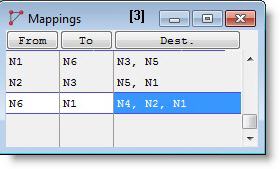
From Entities and resources traveling out of this node will use this mapping record to decide which of the alternate branches will be taken next.
To The “from” node and the “to” node together define the branch to be taken next. This might also be interpreted as the node which entities and resources will go through, to reach one of the destination nodes.
Dest. Entities and resources whose ultimate destination is one of these nodes will be forced to take the branch that directly connects the “from” node to the “to” node.
Please Note: When your simulation is compiled and run,
How to create mappings using the mapping edit table:
How to create mappings graphically:
Please Note:
An example of mapping two branches of a network is given on the following pages.
The following example uses a path network diagram to demonstrate mapping.
In this example, we wish to force resources and entities enroute from Loc1 to Loc4, Loc5, or Loc6 to take the branch directly connecting node N2 and node N5 to avoid traffic congestion at the intersection of the two main branches at node N3. Since there are multiple ways to go from N2 to N5, a decision as to which alternative will be used has to be made at N2.
In addition, we want resources and entities to follow the same path in the opposite direction when enroute from Loc4, Loc5, or Loc6 to Loc1. In this case, the decision must be made at N5.
Because the combined length of segments connecting N2 to N3 and N3 to N5 is shorter than the length of the single segment from N2 to N5, resources and entities based on speed and distance will normally take the former path to travel. To force them to take the longer path, we must specify mapping constraints.
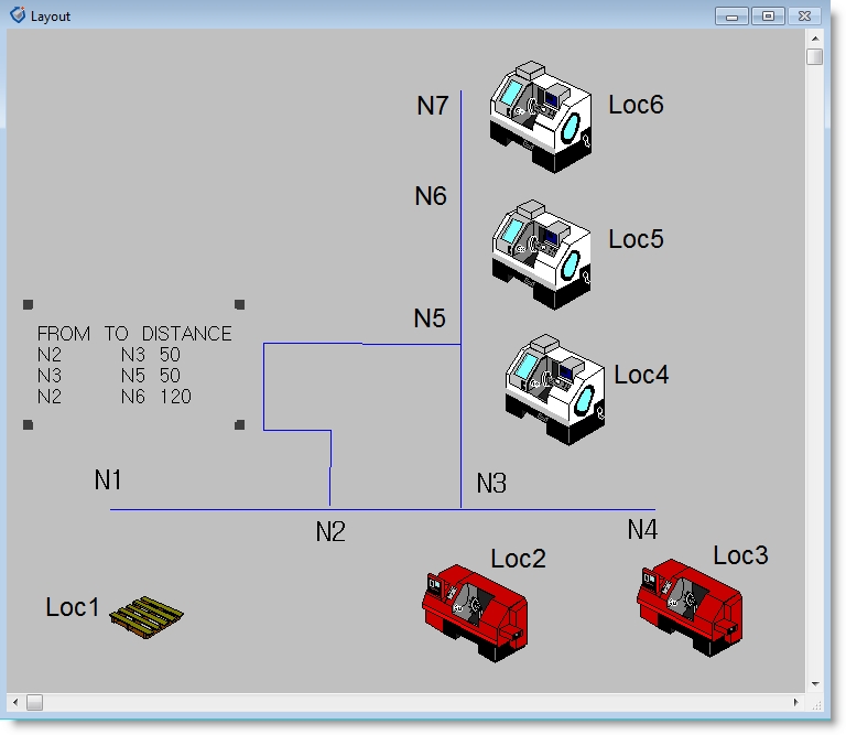
This case requires two explicit mapping constraints to override the selection of default paths in each direction: The first table entry forces entities and resources en-route from Loc1 to Loc4, Loc5, or Loc6 to override the default path and take the direct branch from N2 to N5. The second table entry forces entities and resources traveling from N5 (originally from Loc6, Loc5 or Loc4) to Loc1 to take the direct branch from N5 to N2. Entries 3 and 4 are optional, and might be useful to speed up translation, since the restrictions they impose allow the shortest path calculations to be bypassed.
There is a shortcut to force the same non-default path selection constraint to a number of destination nodes: For instance, if the vertical arm of the path network extended up to include many other nodes N8, N9, ..., and locations Loc7, Loc8, ..., then we would change the Mapping edit table as follows:
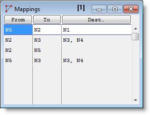
The empty destination column will be interpreted as “all other destination nodes” by
Please Note: For a “from” node (unless there is a branch map with a blank destination column), any nodes not explicitly listed in the destination columns of existing mapping records will be reached via the default path selections.

|
© 2012 ProModel Corporation • 556 East Technology Avenue • Orem, UT 84097 • Support: 888-776-6633 • www.promodel.com |